Restoration Philco C-5109 (Mopar 815) Car Radio

Philco C-5109 (Mopar 815) Car Radio
One of the latest restoration I had the pleasure to do was of an interesting and unusual American car radio set by Philco – MOPAR (Mopar was – and is still nowadays – the spare part division of the American car maker Chrysler).

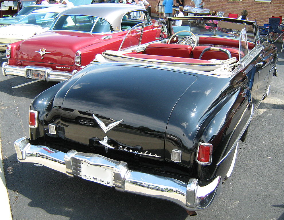
The model is Philco C-5109 (Mopar 815), installed in the cars Chrysler Windsor, Saratoga, New Yorker in 1951-52.

Chrysler New Yorker 1951 - Wikimedia Commons Chrysler New Yorker 1951 dashboard with radio - Wikimedia Commons

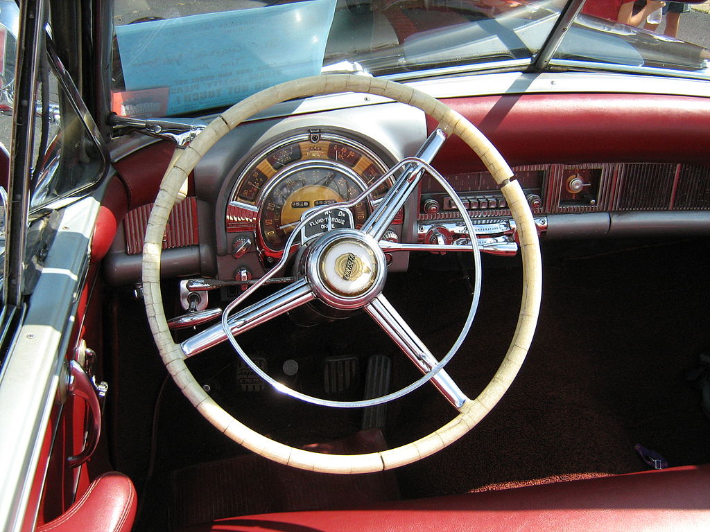
It is indeed a set of the early ’50s, running at 6 volts, with 8 tubes and able to receive standard broadcast only. Beyond the manual tuning, it has 5 pre-tuned stations which can be selected with the nice chromium-plated push-button panel.The audio amplifier includes a push-pull output stage with two 6AQ5, driven by a 6C4 phase inverter triode, in this case the grids of the output tubes are connected respectively one to the cathod and the other to the anode of the triode.

The high-voltage power supply stage of the anode, like all other car radios of this time, is equipped with an electromechanical inverter, known as vibrator and with a concept similar to door bells and buzzers, whose tasks is to transform the direct current of the battery into alternating current, creating a square waveform. This is then sent to a transformer to increase the voltage up as needed. A rectifier tube transform the current out from the transformer into direct current, so that it can be used to power up the tubes. Thanks to the (square) waveform, the filter capacity doesn’t need to be high: in fact, the electrolytic capacitors are rather small.
The circuit is split among two separate chassis: the first contains the radio part, the tuning dial, the knobs and buttons, and therefore was supposed to be installed on the dashboard or the console of the car; the second contains the power supply, audio amplifier and loudspeaker, and was meant to be hidden below the dashboard.
The different locations are clearly shown by the conditions of the two parts: the former is nearly perfect, whereas the latter was very dirty and rusted.
The kind owner sent me the radio since, after several working hours, it had suddenly stopped working. According to the description of the radio, it was a preserved set (which means, unrestored), so I had to warn that a lot of work might have been necessary despite the fact it had been working until recently.Radios of this period, in particular American ones, suffers from the well-known problem of paper capacitors which, being hygroscopic, they show the deleterious effects of imperfect sealing with the age, causing several kind of faults and problems, such as shorts, tube overheating, wrong polarization, etc. Moreover, this set uses a lot of carbon composition resistors, which tends to go out of tolerance with the time.
At the arrival of the parcel, my guesses were confirmed: as shown in the photos, there were not only rust and oxydation, but also several dead insects, mice ejecta, etc.), so it had to be washed and thoroughly cleaned before any restoration attempt.
After drying the radio, I tried to power it up: I normally use a dual power supply from my lab instruments, able to supply 3 ampere, which was going into overload protection because of the radio. I wasn’t sure whether this was normal or not, and since I hadn’t at the moment anything able to supply higher current, so I decided to continue in a different way.
PC power supplies are able to supply hundreds of watt, so dozens of ampere at 5 / 12 volt. I had already adapted one of these in order to power up another 12 volt car radio, following the instructions which can be easily found online (power-up signal on the green wire, dummy load, etc.), but in that case the 12 volt was already available as standard output. A 6 volt output wasn’t, so I decided to obtain it from the 5 volt one. The idea was to increase the 5 volt tension as needed, tweaking the feedbacked circuit which is measuring the output voltage, modifying the voltage divider. Since most of these power supplies use one or two integrated circuits to control the whole device, we just need referring the datasheet of this part and look for the sense circuit of the output voltage. Once I found the desider resistor, I added a suitable potentiometer in series, in order to be able to increase resistance value and adjust the output voltage within a certain limit.
Once the 6 volt – 30 ampere power supply was ready, I powered the radio up and could verify that the current drawn was over 8 ampere, which was undoubtedly anomalous. Removing the vibrator, the current drawn decreased to a normal 2-3 ampere, which meant that the fault was on the circuit connected to it. In fact, the problem was due to a shorted paper capacitor at the secondary winding of the step-up transformer between the vibrator and the rectifier. This part was probably meant to reduce the switching noise, to avoid that it could disturb the radio reception: located at the secondary terminal, it is subjected to the maximum AC voltage with a square wave and is therefore the most stressed component.
Once replaced, the radio started to work, but there were still some problems. The triode 6C4, being connected to the anode of the preceding tube with a paper capacitor, was working the 6C4 at +7 volt on the grid (instead of the 0 required) because of this fault. Moreover, also the capacitors from the 6C4 to the two output tubes were in the same conditions. With their replacement together with two resistors which were out of tolerance, the radio started to work much worse, with very strong distortion and very low volume. Very strange behavior, since the output stage circuits were now repaired. This kind of distortion is normally due to a worn-out 6C4: indeed, reconnecting the old leaking capacitor (which means, +7 volt on the grid and reproducing the fault again), the radio was performing decently. I was wondering whether the 6C4 got “used to” work in these conditions and, being completely worn-out, needed to work with a positive voltage; however, when checked it with a tube tester, it was still perfectly efficient! I was really puzzled, this was giving me a real headache…

After much thought and looking up the datasheet of the 6C4, the anode of the triode is connected to the pins no. 1 and 5; in our radio the connections were soldered only to the pin no. 1 of the tube socket. I tried to connect the 1 and 5 pins of the socket with a jump wire, and the radio started to perform well and strong: the internal connection in the tube between the two pins must have been interrupted! Once restored the connection between the two pins in the socket, the problem was solved.
Already while opening the chassis of the RF-IF part, we can appreciate the accuracy of the assembly. Only few minutes of operation, however, another capacitor started to smoke, this time in the RF-IF chassis. This meant that there was further work to be done. I decided to replace all the capacitors which decouple a higher voltage from a point with a lower voltage. After this, the anode voltage increased by over 30 volts, a sign that the leakages were considerable.

Unfortunately the potentiometer of the tone control was in series with a leaking capacitor, also connected to an anode of a tube. These American capacitors, when leaking, show a really strong leakage, so the potentiometer was reached by 70 volt, enough to cut it off. Since it was still partly working, and it was difficult to disassemble it, I left it untouched, but added a resistor with same value in parallel, to avoid breaking the circuit where it was inserted. This radio has a negative feedback to improve the audio quality and the reducing the distortion.

Most resistors were out of tolerance, but the radio was already working very well, so their replacement was unnecessary.
After cleaning and lubricating the mechanical parts, I decided to align the intermediate frequencies at 455 kHz, discovering that they were still perfectly tuned, despite many years and the vibrations in a car of this age!
On completion of the work, the reception is great, the radio is very sensitive, the audio quality and output power are extraordinary, as a proof how things at the time were made to last.

Leave a Reply

This site uses Akismet to reduce spam. Learn how your comment data is processed.